 ▼
▼
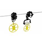
Double Support Tie

Double Support Ties provide a vastly improved method of securing conductor in the top groove of interchangeable headstyle insulators in double insulator construction applications. The loop of the Double Support Tie has been engineered so "C" and "F" insulators can be accommodated by a single tie design. A separate design is required for "J" neck insulators. Each Double Support Tie is supplied with elastomer tie tubes designed to minimize abrasion to bare conductor and insulators.
-
Applicable to interchangeable headstyle insulators - C, F, and J-Neck
-
Accommodates conductors from 0.245" - 1.240" diameter
-
Pre-contoured Tie ensures a tight fit
-
Mitigates long-term issues caused by Radio Influence Voltage (RIV)
-
Accommodates line angles up to 80-degrees (40-degrees per Insulator)
-
Exceeds NESC requirements for unbalanced load
-
Reduces or eliminates abrasion caused by vibration
-
Ideal for severe weather applications and system hardening activities
-
Resiliency of the tie protects the conductor
-
Test reports available upon request
Product Information
Double Support Tie - Catalog Pages
Installation Instructions
SP-2217 (Double Support Tie - Hairpin Style)
SP-3386 (Double Support Tie - Tabbed Style)
SP-3387 (Tabbed Style vs. Hairpin Style) Letter of Design Reinstatement
|
Diameter Range1 |
Nominal Conductor Size2 | Units per Carton | C-Neck Insulators (Black) | J-Neck Insulators (Green) | Conductor Color Code | Tie Type | ||||
| in | Catalog Number | Applied Length | Catalog Number | Applied Length | ||||||
| Minimum | Maximum | in | in | |||||||
| 9/16" R. Groove4 | ||||||||||
| 0.245 | 0.277 |
#4, 6/1, 7/1; #4, 7W Alum. Alloy |
50 | DST-0150 | 13 | DST-0350 | 14 | Orange | Tabbed | |
| 0.278 | 0.315 |
#3, 7W Alum. Alloy; #2, 7W All Alum. |
50 | DST-0151 | 13 | DST-0351 | 14 | Purple | ||
| 0.316 | 0.357 |
#2, 6/1, 7/1; #2, 7W Alum. Alloy; #1, 6/1 ACSR |
50 | DST-0152 | 14 | DST-0352 | 15 | Red | ||
| 0.358 |
0.405 |
1/0, 7W All Alum.; 1/0, 6/1 ACSR; 1/0, 7W Alum. Alloy |
50 | DST-0153 | 14 | DST-0353 | 15 | Yellow | ||
| 0.406 | 0.459 |
2/0, 7W All Alum.; 2/0, 6/1 ACSR; 2/0, 7W Alum. Alloy |
50 | DST-0154 | 15 | DST-0354 | 16 | Blue | ||
| 0.460 | 0.520 |
3/0, 7W All Alum.; 3/0, 6/1 ACSR; 3/0, 7W Alum. Alloy |
50 | DST-0155 | 16 | DST-0355 | 16 | Orange | ||
| 0.521 | 0.588 |
4/0, 7W All Alum.; 4/0, 6/1 ACSR; 4/0, 7W Alum. Alloy |
50 | DST-0156 | 17 | DST-0356 | 18 | Red | ||
| 0.589 | 0.665 |
266.8, 37W All Alum.; 266.8, 18/1 |
50 | DST-0157 | 17 | DST-0357 | 18 | Purple | ||
| 9/16" R. Groove4 | ||||||||||
| 0.666 | 0.755 | 336.4, 19W All Alum.; 336.4, 18/1; 397.5, 19W All Alum. | 50 | DST-0158 | 18 | DST-0358 | 19 | Brown | Tabbed | |
| 0.756 | 0.858 |
477, 19W, 37W All Alum.; 477, 18/1 24/7, 26/7 |
50 | DST-0159 | 20 | DST-0359 | 21 | Red | Hairpin | |
| 5/8" R. Groove4 | ||||||||||
| 0.859 | 0.968 |
556.5, 26/7; 636, 18/1; 700, 37W, 61W All Alum. |
25 | DST-0160 | 21 | DST-0360 | 22 | Blue | Hairpin | |
| 3/4" R. Groove4 | ||||||||||
| 0.969 | 1.096 |
795, 37W All Alum.; 795, 61W All Alum.; 715.5, 24/7; 795, 54/7 |
25 | DST-0161 | 22 | DST-0361 | 23 | Green | Hairpin | |
| 1.097 | 1.240 |
954, 36/1, 54/7; 1033.5, 37W, 61W All Alum. |
25 | DST-0162 | 23 | DST-0362 | 24 | Yellow | ||
|
Right-hand lay standard NOTES: 1 Diameter Range indicates the size of conductors that utilize the same tie. 2 Nominal Conductor Size indicates one or more of various conductors within each range. 3 The loop of the Double Side Tie can accommodate either C, F, or J-Neck insulators as indicated in the table. 4 For the succeeding ranges the insulator's side groove radius should be at least as large as shown above. |
||||||||||