 ▼
▼
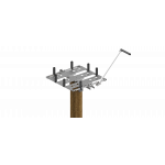
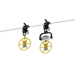
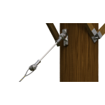
EZ-WRAP® Twin Tie

EZ-WRAP Twin Ties provide a vastly improved method of securing conductor compared to clamp-top insulators or hand ties over Armor Rods. They provide superior abrasion protection for the conductor under all types of motion, including low-frequency sway oscillation, high-frequency aeolian vibration, and galloping. The tube component surrounds the bare conductor with a resilient cushion where the conductor would come into contact with the insulator.
-
Applicable to interchangeable headstyle insulators - C, F, and J-Neck
-
Accommodates conductors from 0.245" - 1.240" diameter
-
Pre-contoured Tie ensures a tight fit
-
Mitigates long-term issues caused by Radio Influence Voltage (RIV)
-
Accommodates line angles up to 10-degrees in the vertical orientation
-
Exceeds NESC requirements for unbalanced load
-
Reduces or eliminates abrasion caused by vibration
-
Ideal for severe weather applications and system hardening activities
-
Resiliency of the tie protects the conductor
-
Test reports available upon request
-
Non-rotational tie for installing on insulators with limited clearance
Product Information
EZ-WRAP Twin Tie - Insulator Ties Catalog Pages
Insulator/Tie Fit Information Sheet
Installation Instructions
|
Diameter Range |
Nominal Conductor Size1 | Units per Carton | C- and F-Neck Insulators (Black and Yellow) | F- and J-Neck Insulators (Yellow and Green) | Conductor Color Code | |||||
| in | Catalog Number | Applied Length | Catalog Number | Applied Length | ||||||
| Minimum | Maximum | in | in | |||||||
| 0.245 | 0.277 |
#4, 6/1, 7/1; #4, 7W Alum. Alloy |
50 | TTCF-102 | 13 | TTFJ-202 | 14 | Orange | ||
| 0.278 | 0.315 |
#3, 7W Alum. Alloy; #2, 7W All Alum. |
50 | TTCF-103 | 13 | TTFJ-203 | 14 | Purple | ||
| 0.316 | 0.357 |
#2, 6/1, 7/1; #2, 7W Alum. Alloy; #1, 6/1 ACSR |
50 | TTCF-104 | 14 | TTFJ-204 | 15 | Red | ||
| 0.358 | 0.405 |
1/0, 7W All Alum.; 1/0, 6/1 ACSR; 1/0, 7W Alum. Alloy |
50 | TTCF-105 | 14 | TTFJ-205 | 16 | Yellow | ||
| 0.406 |
0.459 |
2/0, 7W All Alum.; 2/0, 6/1 ACSR; 2/0, 7W Alum. Alloy |
50 | TTCF-106 | 15 | TTFJ-206 | 16 | Blue | ||
| 0.460 | 0.520 |
3/0, 7W All Alum.; 3/0, 6/1 ACSR; 3/0, 7W Alum. Alloy |
50 | TTCF-107 | 16 | TTFJ-207 | 17 | Orange | ||
| 0.521 | 0.588 |
4/0, 7W All Alum.; 4/0, 6/1 ACSR; 4/0, 7W Alum. Alloy |
50 | TTCF-108 | 16 | TTFJ-208 | 17 | Red | ||
| 0.589 | 0.665 |
266.8, 37W All Alum.; 266.8, 18/1 |
50 | TTCF-109 | 17 | TTFJ-209 | 18 | Purple | ||
| 9/16" R. Groove2 | ||||||||||
| 0.666 | 0.755 |
336.4, 19W All Alum.; 336.4, 18/1; 397.5, 19W All Alum. |
50 | TTCF-110 | 18 | TTFJ-210 | 19 | Brown | ||
| 0.756 | 0.858 |
477, 19W, 37W All Alum.; 477, 18/1 24/7, 26/7 |
50 | TTCF-111 | 18 | TTFJ-211 | 19 | Red | ||
| 5/8" R. Groove2 | ||||||||||
| 0.859 | 0.968 |
556.5, 26/7; 636, 18/1; 700, 37W, 61W All Alum. |
50 | *TTF-112 | 20 | *TTJ-212 | 21 | Blue | ||
| 3/4" R. Groove2 | ||||||||||
| 0.969 | 1.096 |
795, 37W All Alum.; 795, 61W All Alum.; 715.5, 24/7; 795, 54/7 |
50 | *TTF-113 | 21 | **TTJ-213 | 22 | Green | ||
| 1.097 | 1.240 |
954, 36/1, 54/7; 1033.5, 37W, 61W All Alum. |
50 | *TTF-114 | 22 | **TTJ-214 | 23 | Yellow | ||
|
* These sizes are recommended for use with F-Neck insulators ONLY due to C-Neck insulator top groove space limitations. ** These sizes are recommended for use with J-Neck insulators ONLY. Right-hand lay standard NOTES: 1 Nominal Conductor Size indicates one or more of various conductors within each range. 2 For the succeeding ranges the insulator's top groove radius should be at least as large as shown above. |
||||||||||